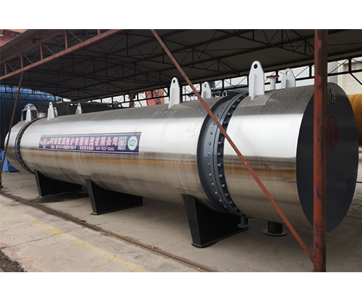
Floating head heat exchanger
The floating head end structure of floating head heat exchanger is composed of cylinder, outer head cover side flange, floating head tube plate, hook ring, floating head cover, outer head cover and screw hole, steel ring, etc., which is characterized in that: concave or ladder sealing surface is set on the inner side of outer head cover side flange, and holes are drilled and threaded or multiple screws are welded on the outer side near the sealing surface, and hook ring and related parts are canceled at the floating head, The floating head tubesheet sealing groove is the original concave groove and another trapezoidal groove with the tubesheet center as the center and a radius slightly greater than the outer diameter of the tube bundle is opened on the same end face, and the tubesheet pass groove is only connected with the trapezoidal groove, not with the concave groove.
Structural performance:
The tube plate at one end of the floating head heat exchanger is fixed between the shell and the header, and the tube plate at the other end can move freely in the shell. This feature can be seen on the site. The heat expansion of the shell and the tube bundle of the heat exchanger is free, and the tube bundle can be drawn out to facilitate the cleaning between tubes and inside tubes. The disadvantage is that the structure is complex, the cost is high (20% higher than the fixed tubesheet), and leakage occurs at the floating head during operation, which is difficult to check and handle. The floating head heat exchanger is applicable to the conditions where the temperature difference between the shell and the tube bundle is large or the shell side medium is easy to scale.


